
How to read a P&ID: lines, valves, instruments and tags
A practical guide to reading piping and instrumentation diagrams: line numbers, valve and instrument symbols, ISA tag letters, and a step-by-step way to work through a sheet.
A piping and instrumentation diagram packs a lot of information into one sheet: every line, valve, instrument and safety device of a unit. It looks dense at first, but it follows conventions. Once you know them, a P&ID reads like a map. Symbols and numbering vary between companies, so always check the legend sheets of the project you are working on; the conventions below are the common ones, largely based on ANSI/ISA-5.1.
Start with the legend and title block
Most projects issue legend sheets that define every symbol, line type, abbreviation and numbering format used. The title block on each sheet gives the unit, drawing number, revision and status. Revision clouds and triangles mark what changed since the last issue, and notes or “holds” flag open items.
Lines and line numbers
Each process line carries a line number. A common format combines size, service, a sequence number, the piping class and an insulation code, for example:
6″-P-1001-A1A-H
Here a 6-inch process line, number 1001, in piping class A1A, heat-conserved. The piping class defines the material, pressure rating and allowed components. Where the class changes along a line, a spec break symbol shows the boundary. Every line on the P&ID also appears in the line list.
Line types distinguish what a line carries. Typical conventions:
| Line | Usually means |
|---|---|
| Thick solid | Main process line |
| Thinner solid | Secondary process or utility line, or an instrument process connection |
| Dashed | Electrical instrument signal |
| Solid with double cross-hatches (//) | Pneumatic instrument signal |
Valves
Most valve symbols are built on a “bow-tie” of two triangles meeting at a point, with a variation inside or on top to show the type: a solid dot for a globe valve, a circle for a ball valve, and so on. Check valves show the allowed flow direction. A control valve adds an actuator on top, often a dome for a diaphragm actuator, and is tagged with its loop, such as FV for a flow control valve. Pressure safety valves (PSV) are drawn with a spring symbol and are always worth finding early on a sheet.
Instruments and tag letters
Instruments appear as circles, or “bubbles”, with a tag inside. The first letter is the measured or initiating variable; the following letters describe what the instrument does. The number ties it to its loop.
| First letter | Variable | Following letter | Function |
|---|---|---|---|
| F | Flow | I | Indicate |
| L | Level | C | Control |
| P | Pressure | T | Transmit |
| T | Temperature | A | Alarm (often with H or L for high or low) |
| A | Analysis (composition) | V | Valve or final element |
| S | Speed | E | Primary element (sensor) |
So:
- FT-101 is a flow transmitter in loop 101, FIC-101 the flow indicating controller, and FV-101 the flow control valve it moves.
- LT-205 is a level transmitter, and LAH-205 a high-level alarm.
- TE-310 is a temperature element such as a thermocouple, usually in a thermowell.
The bubble’s border shows where the function lives. A plain circle is mounted in the field. A circle with a solid horizontal line is in the control room, accessible to the operator. A circle inside a square shows a function in the shared control system, such as a DCS.
Equipment
Equipment is drawn with simplified outlines and tagged with a letter prefix and number, for example P for pumps, V for vessels and drums, E for heat exchangers and T or C for columns. Prefixes vary between companies. Nozzles, with their sizes, connect lines to equipment, and spare or standby equipment is shown alongside, such as pumps P-101A and P-101B.
A way to work through a sheet
- Find the inlet and outlet. Off-sheet connectors show where lines come from and go to; follow the main process route from feed to product first.
- Trace the control loops. For each control valve, find its controller and transmitter. Ask what it controls and what it manipulates.
- Find the protection. Locate relief valves, trips and interlocks, and check every vessel that can be overpressured has protection.
- Check the details. Drains, vents, sample points, spec breaks, insulation and tracing, slopes and notes.
- Compare with the PFD. Stream numbers, equipment and conditions should match the process flow diagram and the heat and material balance.
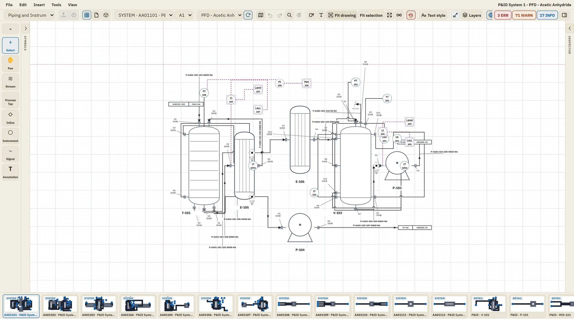
Keeping P&IDs consistent
The hardest part of P&IDs is keeping them consistent with the PFD, the balance and the line list as the design changes. In Black Owl, P&IDs are developed in the same project as the flow diagrams, with piping classes defined once and a PFD line list and DEXPI module in the workspace. Request early access, or see how BFDs, PFDs and P&IDs fit together and the glossary.