
BFD vs PFD vs P&ID: what each process diagram is for
Block flow diagrams, process flow diagrams and piping and instrumentation diagrams describe the same plant at three levels of detail. Here is what belongs on each, and when you need it.
Every process plant is described by a family of diagrams. The three you meet first are the block flow diagram (BFD), the process flow diagram (PFD) and the piping and instrumentation diagram (P&ID). They describe the same process, but at very different levels of detail and for different people. Mixing them up is one of the most common sources of confusion, and rework, in early engineering.
Block flow diagram (BFD)
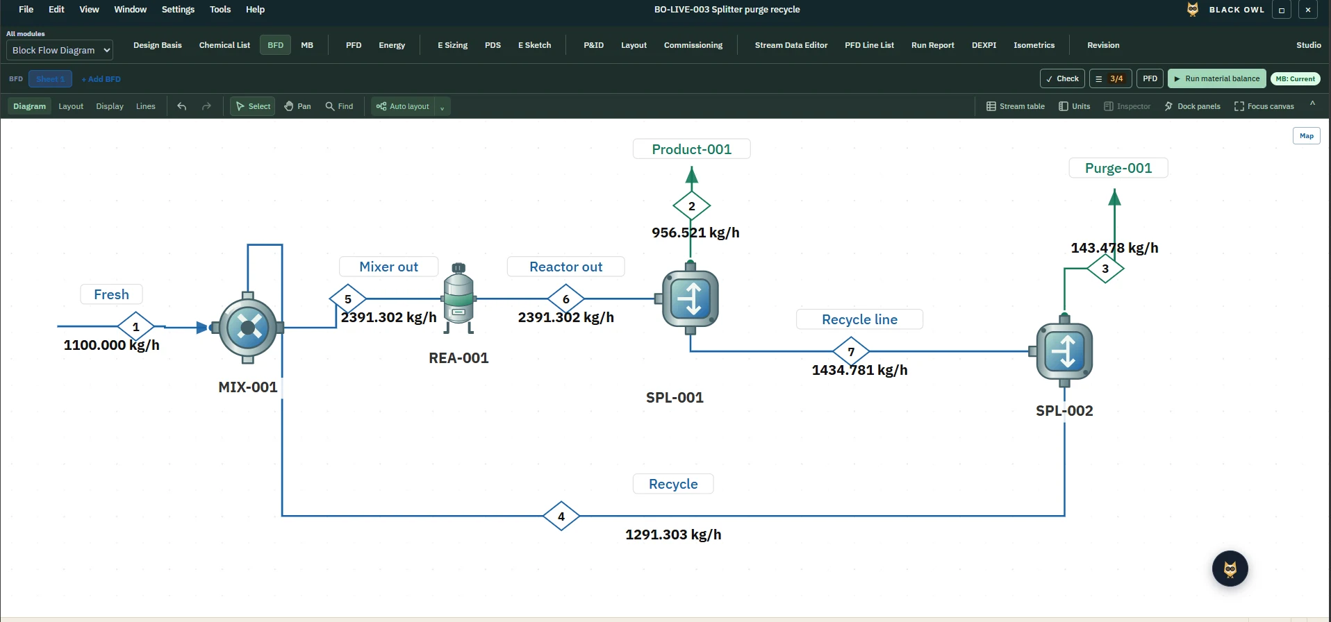
A BFD shows the process as a small number of blocks, one for each major step such as feed preparation, reaction, separation and purification, joined by arrows for the main streams. It answers one question: what happens to the material, in what order?
- Blocks for process steps or units, not individual pieces of equipment.
- Main feed, product, recycle and by-product streams.
- Often an overall material balance: flow rates on the key streams.
BFDs belong to the conceptual and feasibility stage. They are quick to change, which is exactly what you want while the process route is still being chosen.
Process flow diagram (PFD)
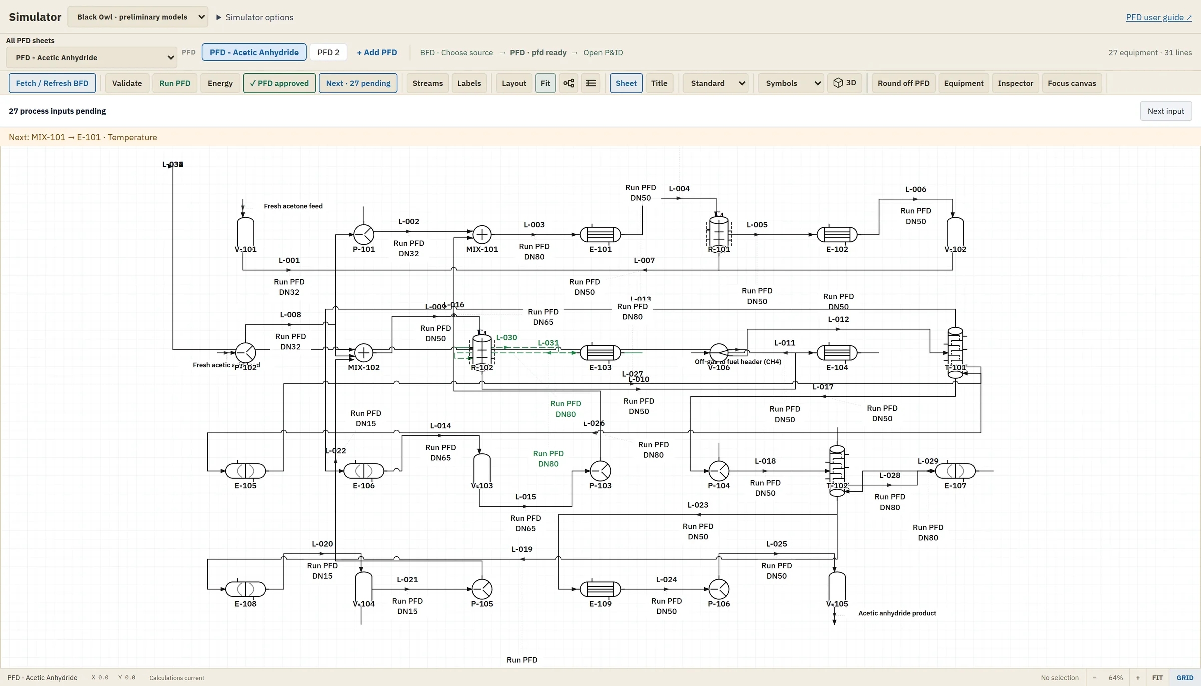
A PFD replaces blocks with the major equipment: pumps, vessels, heat exchangers, reactors and columns, and shows the main process lines between them. It is the central document of basic engineering.
- Major equipment with identification tags.
- Numbered process streams, usually with a stream table or heat and material balance: flow, temperature, pressure, phase and composition.
- Key operating conditions and, often, the main control loops.
- Utility connections such as cooling water and steam at the equipment that uses them.
The PFD is what equipment sizing works from. If a pump, exchanger or column is not on the PFD, it has not been designed yet.
Piping and instrumentation diagram (P&ID)
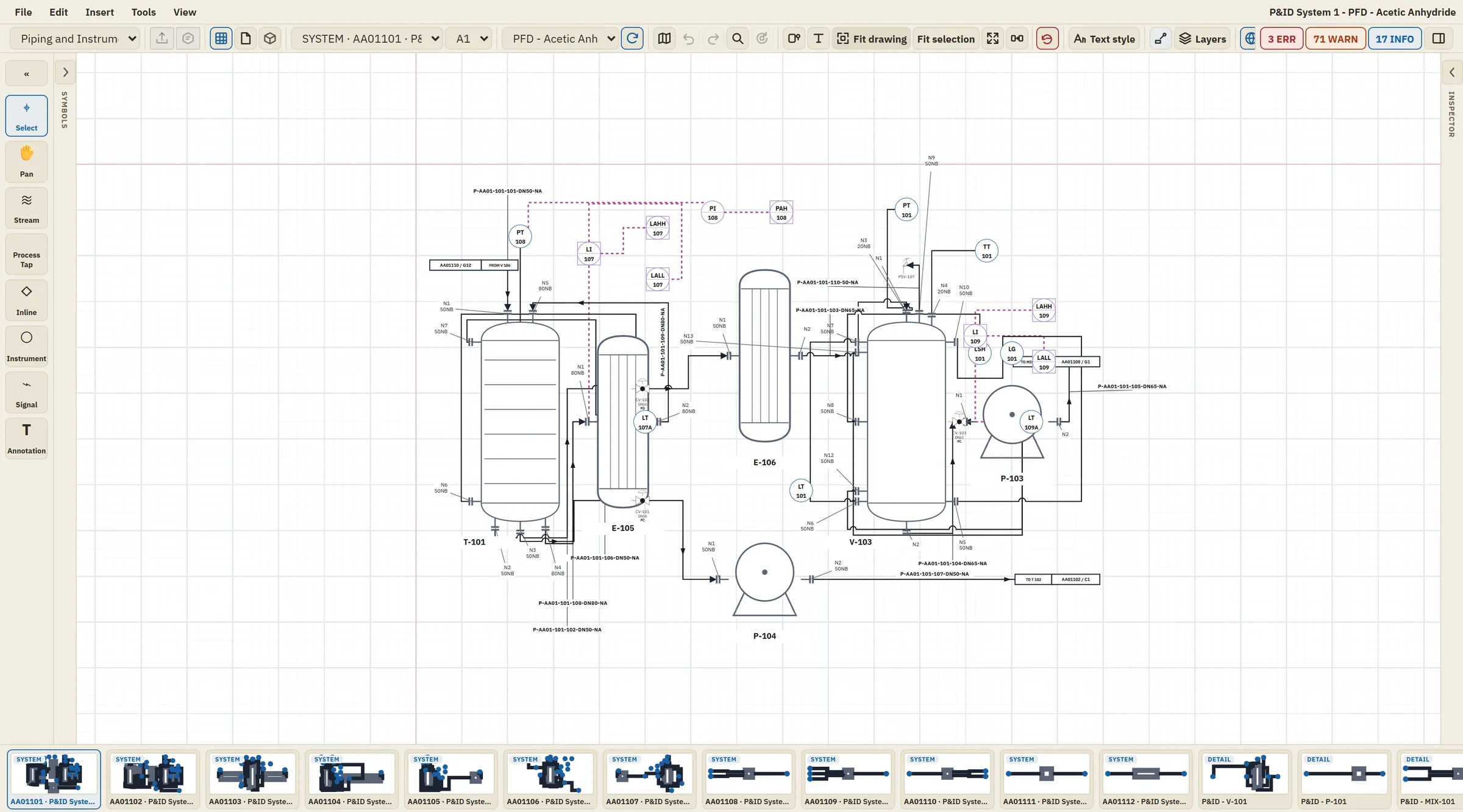
A P&ID shows everything needed to build, check and operate the piping system. It is the most detailed of the three and the basis for detailed design, safety reviews such as HAZOP, construction and operation.
- All piping, with line numbers, sizes and piping class (material and pressure rating).
- Every valve, including manual, control and check valves.
- Instruments and control loops, usually drawn with ISA-5.1 symbols and tag numbers.
- Safety devices such as relief valves, plus vents, drains and sample points.
- Equipment nozzles, insulation and tie-ins to other units.
Side by side
| Aspect | BFD | PFD | P&ID |
|---|---|---|---|
| Question it answers | What steps, in what order? | Which equipment, at what conditions? | How exactly is it piped, controlled and protected? |
| Project stage | Concept and feasibility | Basic engineering | Basic into detailed engineering |
| Shows | Blocks and main streams | Major equipment, process streams, balance | All lines, valves, instruments, safety devices |
| Main users | Process and project teams | Process, mechanical and cost engineers | All disciplines, HAZOP teams, operations |
Three common mistakes
- Putting P&ID detail on the PFD. Valves, drains and every instrument make a PFD hard to read and slow to change. Keep the PFD about the process.
- Letting the diagrams drift apart. A stream renamed on the PFD but not on the P&ID, or a balance that no longer matches the flowsheet, is a classic source of error. Revisions must move together.
- Skipping the BFD. Going straight to a PFD hides the overall material balance and makes route changes expensive. A one-page BFD is cheap insurance.
Standards worth knowing
ISO 10628 covers diagrams for the chemical and petrochemical industry, including flow diagram types and graphical symbols. ANSI/ISA-5.1 defines instrumentation symbols and identification. DEXPI is an industry initiative for exchanging P&ID data between software tools. Your client or company standard usually decides which apply.
Keeping them connected
The three diagrams are views of one process, so they work best when they come from one project record. That is the idea behind Black Owl: the block flow diagram, material balance, process flow diagram and piping and instrumentation diagram live in the same project, so a change in one place is visible everywhere. Request early access to see it on your own process.